Pressure vessels are among the most important components of industrial plants in the oil and gas, petrochemical, power generation, and refining industries. These vessels are designed for the storage and transport of liquids at pressures above atmospheric pressure. Safety and leak tightness play a central role in these systems, as do the primary fastening elements in the design and manufacture of pressure vessels. Flanges not only connect various vessel components but also facilitate disassembly, inspection, repair, and maintenance. The correct selection of flanges—in terms of type, material, size, and specifications—is crucial for the vessel’s longevity and safety.
Definition of lips and their function in pressure vessels
A flange is a round component that is bolted to another flange on one side, typically with a gasket in between. In pressurized systems, flanges are used to create detachable connections between tanks, nozzles, covers, valves, and pipelines
. The main functions of flanges in these systems are:
-
It forms a strong, waterproof bond that withstands pressure and temperature.
-
Fast on/off switching process for inspection or maintenance.
-
Absorption of thermal and mechanical stresses between different components
-
Assistance with the assembly and disassembly of heavy equipment
Types of seals used in pressure vessels
Pressure vessel flanges are generally classified into different categories depending on the type of connection, design, and sealing surface:
1. Welded neck
The most commonly used flange in high-pressure vessels. This flange has a conical neck that gradually transfers the pressure load to the pipe wall or vessel body. A full weld is used between the flange and pipe for maximum strength and insulation.
Advantages: High pressure and temperature resistance, as well as high centering accuracy.
Application: High-pressure nozzles and main inlets and outlets of high-pressure vessels.
2. Empty game board
Blind flanges are used to seal nozzle openings or tank ends. In high-pressure tanks, they are typically used in areas requiring regular internal inspections.
Advantages: Complete internal sealing of the tank.
Application: Covers for nozzles or inspection openings.
3. Sliding lip
A flange through which a pipe passes and which is joined by two welds – one inner and one outer. Despite its simple assembly, it is not typically used in high-pressure applications.
Advantages: Quick and cost-effective installation.
Applications: Low-pressure systems or medium-pressure vessels.
4. Socket welding flange
In this connection method, the pipe is inserted into the flange up to the bottom of the bore and then welded to the outer flange. It is suitable for small-diameter high-pressure pipes and is used in precision instrument connections and elbows
.
5. Thread projection
It has an internal thread and can therefore be connected to pipes without welding. However, due to the risk of leakage at high pressures, its use in pressure vessels is limited.
Applications: temporary connections or test sections.
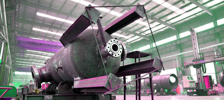
The final lip type
The contact surface between the two edges onto which the seal is placed is called the contact surface. The type of contact surface is crucial for the seal.
-
Pressure rating (FF): Pressure rating suitable for low-pressure environments.
-
Convex surface (CS): possesses a central convex surface that ensures even pressure distribution in the joint.
-
RTJ (Ring Connection): Ring groove for metal connections; suitable for environments with extremely high pressure and extremely high temperatures.
-
Tongue and groove connection: The tongue and groove connection ensures a more precise seal.
RTJ end seals are frequently used in high-pressure vessels because the metal seal is pressed firmly into the groove under pressure, thus forming a reliable seal.
Standards for the edge design of pressure vessels
The flange design must comply with international standards to ensure safety, interchangeability, and durability. Common standards include:
-
ASME Volume 8, Part 1: Design and Construction of Pressure Vessels
-
ASME B16.5: Applies to steel wheels with a maximum dimension of 24 inches.
-
ASME B16.47: Applies to edges longer than 24 inches.
-
MSS SP-44: Transition pipe flange
-
EN 1092-1: European standard for edges.
-
API 6A: Applicable to equipment for oil and gas drilling under extremely high pressure.
When designing a tank, the rim type, wall thickness, size, number of bolts, design pressure and operating temperature are determined based on these parameters.
Materials used in the manufacture of high-pressure flanges
The choice of materials for pressure vessel flanges depends on the operating pressure, temperature, type of medium, and its corrosion resistance . The most commonly used materials include:
-
Carbon steel (A105): General purpose
-
Stainless steel (304/316): suitable for aggressive and hygienic liquids.
-
Alloy steel (F11, F22): is used at high temperatures.
-
Double steel and super double steel: exhibit excellent resistance to chloride corrosion.
-
Nickel-titanium alloys: Suitable for special chemical applications or extremely high temperatures.
Choosing the wrong material can lead to cracks, leaks, or even the failure of the entire system , which is why this step is particularly important.
Edge processing in pressure vessel manufacturing
The flange manufacturing process must be extremely precise to ensure that dimensional tolerances and surface finish meet standards. Key manufacturing processes include:
-
Grinding the sealing surface: to achieve a suitable roughness (usually 3.2–6.3 µm Ra).
-
Chamfering the neck and inner surface: for more precise welding.
-
Precision drilling and tapping: Used to assemble screws and nuts according to standard patterns.
-
Grinding: Ensure correct alignment and avoid leaks.
-
Quality control of dimensions and appearance: using calipers, micrometers and non-destructive testing methods.
How to attach a lip to an oil tank
In high-pressure vessels, the rim is usually connected to the vessel body as follows:
-
Full penetration welding: According to ASME requirements, this is the most reliable joining method.
-
Welds: Suitable for low-pressure connections or non-critical connections.
-
Threaded connection: Suitable only for low-pressure devices and lines.
Flange welds must be inspected and approved by a certified welding inspector. Additionally, non-destructive testing methods such as radiographic (RT) or penetrant (CT) testing are performed to ensure weld quality.
Calculation of lip lift and design
When designing flanges for high-pressure vessels, three main types of pressure are taken into account:
-
Peripheral voltage
-
Stretching of the lip frenulum
-
Stresses caused by the force of the screws and the internal pressure
The calculation equations are defined in Section 8 of Appendix 2 of the ASME Code or in ASME B16.5. These calculations are used to determine the flange thickness, bolt diameter, and gasket stiffness to ensure a leak-free connection at design pressures.
Choose the correct seal.
Seals or O-rings are inserted between two sealing lips to ensure a tight seal. In high-pressure vessels, the type of seal depends on the pressure, temperature, and type of medium. The most common seals are:
-
Screw seals: made of stainless steel and graphite; resistant to high pressure.
-
Metallized fillers: with a metallic outer coating and a flexible core; suitable for RTJ surfaces.
-
PTFE fillers: resistant to aggressive chemicals
-
Kammprofile seals: a combination of metal and graphite that offers excellent sealing properties.
The use of standard seals and their proper installation is one of the most effective factors in preventing leaks in pressure vessels.
Quality control and lip tests
After the edge has been manufactured and installed, the following tests must be carried out to ensure its proper function:
-
Hydrostatic pressure test: Check for leaks under design pressure.
-
Air or gas leak test (pressure test): Check for leaks at low pressure.
-
Penetration testing (PT): Detection of surface cracks
-
Magnetic Testing (MT): applicable to ferromagnetic materials
-
Surface roughness testing
All these tests must be performed in accordance with ASME Section 8 and using calibrated equipment.
Precautions when using pressure vessel flanges
-
The seal must be mounted concentrically to the edge surface.
-
The screws should be tightened symmetrically and in stages.
-
Avoid hitting the edge or the screws directly with the hammer.
-
After the pressure test, it must be ensured that there are no leaks, cracks or deformations at the edges.
Care and repair of the lips during operation
Over the course of a tank’s lifespan, its edges can be damaged by corrosion, wear, or thermal effects . Maintenance measures include the following:
-
Clean and check the sealing surfaces regularly.
-
The seal must be replaced every time the rim is opened and closed.
-
Ultrasound thickness measurement (ultrasound)
-
Corrosion protection coating of the outer surface
-
Use high-temperature grease to lubricate the screws.
In conclusion
Pressure vessel flanges play a crucial role in safety, leak tightness, and maintenance . The correct flange type, suitable materials, adherence to ASME standards, precise operation, and continuous quality control are critical factors in the design and manufacture of these systems. Ultimately, the more precise the flange design and manufacturing, the higher the performance and service life of the pressure vessel, and the lower the risk of leaks or failures.